- David Ewing
Branson, Missouri, USA 65680
417.546.2090 Office (9am - 9pm Central Standard Time)
Superconductivity Invention presented in the 1994 Tesla Symposium in Colorado Springs, Co. Video tapes were available through the Tesla Society until it shut down some years later.
Common web search terms:
Ambient temperature superconductor
Superconductivity invention
Room temperature superconductor
BACKGROUND OF INVENTION:
It is known that coppers' electron mass at rest is M=9.107 x 10Ż łą. It has odd electrons and is paramagnetic which exhibits magnetic resonance. The magnetic flow in copper brushing the atoms causes atomic vibration which, in turn, produces a ringing effect. When superconductivity is in place, agitation of the atoms is prevented. This allows voltage to flow freely because there is little or no atomic vibration; thus, reducing resistance. Magnetic resonance is a phenomena exhibited by the magnetic spin system of certain atoms, whereby the spin system absorbs energy at a a specific resonant frequency when subjected to an alternating magnetic field. The key factor is that the resonant frequency aligns or stabilizes the atomic vibration much like superconductivity does allowing the atoms to remain in the same place. Likewise, harmonic radio frequency produces the same desired effect.
PROBLEM:
The transmission of electricity using a medium at room temperature is hampered by thermal resistance caused by the mediums atoms oscillating at an unstable rate.
SOLUTION:
By arranging the atoms in synchronous alignment, the transmission of electricity can be accomplished at room temperature without thermal resistance. Radio frequency oscillation aligns the atoms by using an external jacket that surrounds the medium which, in turn, magnetically aligns the atoms allowing the free transmission of electrons. Theoretically, another way to align the atoms in a 60 Hertz signal is to ride the sine wave similar to the way noise travels. The high-frequency signal piggybacks the sine wave and aligns the atomic structure by magnetic waves.
DEVICE:
This $350 working DC prototype utilizes high frequency, high voltage in a manner that feeds back on itself. That is to say, this device uses small amounts of voltage to produce large amounts of energy. The unit works off of 24 VDC that feeds an oscillator producing 2 kV. This feeds across the capacitor and the neon gas bulb. In tests using a 24 VDC battery to feed the oscillator, on one side of the capacitor (-500 VDC) was produced, and on the the other side (-430 VAC).
(Fig. 1)
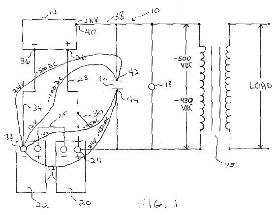
An oscilloscope showed 1.3 volt peak to peak wave feeding the DC side. This by itself was not enough power to maintain the system for long periods of time. However, when the wave fed the positive input back into the device, the energy increased.
High voltage output, either positive or negative, is not normally fed into the positive circuit of a lesser voltage because of thermal degradation due to the resistance. However, when the RF and the voltage are harmonically aligned there is no creation of heat. This unique aspect allows the system to feed back on itself. Tests prove that without the positive feed, the circuit depletes itself within a matter of minutes. With our design, the same circuit will run for months without draining any noticeable power from the battery.
(Fig. 2)
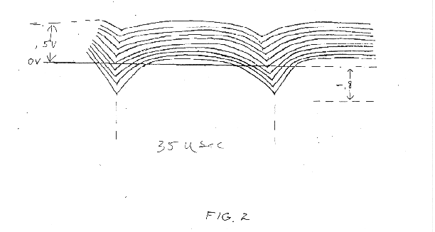
(Fig. 2) shows a multi wave oscillation. The first pulse wave consists of 5 oscillating waves at .5 volt positive to .8 volt negative with a 35 microsecond spread. The wave length is approximately 1000 meters. This wave propagates through the batteries allowing less drain from the load. The second pulse wave duplicates the first. Note: At 500 MV to 800 MV there is not enough energy to produce a change at the moment of use. However, with no load this would take hours to recharge the batteries. This substantiates that the device is not recharging itself, but allowing a harmonic stability to provide less resistance from moment to moment.
(Fig. 3)
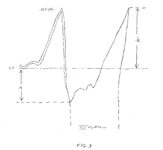
(Fig. 3) shows the negative battery wave to be 10 times oscillated signal at .10 volt peak to peak from zero reference at .6 volt positive to .4 volt negative with a 35 microsecond spread. It is noted however, from Fig.2 to Fig. 3 there is a noticeable .03 volt peak to peak difference.
POTENTIAL:
In the power generation industry, this device should allow a greatly reduced resistance factor in the transmission of electrical energy. It would substantially reduce the amount of "force" needed to transmit electrical potential from one source to another. The amount of energy needed to complete a circuit is decreased because of the positive feed. Other industries interested in this technology would include all manufacturers of electronic devices in telecommunications, computers, consumer products, etc., and of course the military complex! (Presently, this device has been tested and proven in DC, and is theoretical in AC.)
IMPLEMENTATION:
This device has the capability of being install quickly and economically. An estimated cost saving factor is approximately 50-75%! In the power generation industry for example, to get 600 volts to the consumer, the power company must produce 40,000 volts on their end to try to overcome the inherent "line loss" in the miles of wire between them and you.
With our technology in place, 40,000 volt transmission would probably still be the most efficient, but they would only have to produce about half to a quarter as much power as they do now to get the same amount of energy to the consumer. As a beneficial side-effect, the EMF radiation problem they have now should be eliminated as well, and no resistance means no heat! From a cost savings standpoint, every industry should be looking to implement this technology at once, and consumers should demand it!
- Update: 12/98, Walt completely redesigned this circuit, and came up with a 40 watt "Y2K" portable light that would run for 18 hours on a 9 volt rechargeable battery. It runs much longer on larger batteries, and has a built in solar cell for recharging.
I do have the original patent applications, and I have scanned those and put them on a CD. I don't know that there's much more in the application that will help you more than what I have above. The drawings above came right out of the application, and it you're not savvy enough to look at the description and drawings and figure out what you need to do from there, then I have little hope that reading the patent claims are going to tell you what you really need to know.
The total # of pages in the scanned files are 69 pages which I offer on a CD for $100. My contact info is above.